


Silicon wafers are the carriers of most chips. However, a piece of silicon wafer hides many unknown details, such as: What are the crystal orientations of silicon wafers? How many positioning edges are there? How is the positioning edge positioned? What is the difference between the positioning edge and the positioning groove? And so on. Let's explain it in detail today.

What is the positioning edge/groove?
The positioning groove (notch) is used for positioning silicon wafers above 8 inches (inclusive), and the positioning edge (flat) is used for positioning silicon wafers below 8 inches.
The silicon wafer positioning edge is a short side of the silicon wafer, and the positioning groove is a semicircular or V-shaped notch on the edge.

How are the positioning grooves/edges made?
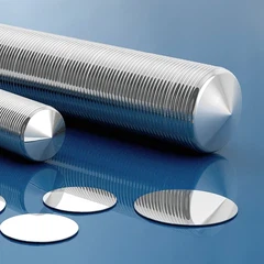
After the CZ method is used to pull out the ingot, the two ends need to be cut off, and then the silicon column is radially ground to obtain a suitable diameter, and then a part of the silicon column is ground to obtain the positioning edge, and finally, the silicon column is cut into silicon wafers one by one with a wire saw or an inner circle cutting machine.
Relationship with crystal orientation & doping
Generally, only the positioning edge has the function of indicating the crystal orientation and doping type. The crystal orientation and doping type of the silicon wafer are determined according to the position and number of the positioning edges. The positioning groove will be at the bottom of the silicon wafer, and the crystal orientation and doping type cannot be intuitively seen through the positioning groove. Common crystal orientations are <100>, <110>, <111>, and the doping types are N-type and P-type.

The number of positioning edges of a silicon wafer is one or two. The type of silicon wafer with only one positioning edge is P-type <111>. If the silicon wafer has two positioning edges, then the longer positioning edge is the main positioning edge, and the shorter one is the secondary positioning edge. The main positioning edge is mainly convenient for the alignment of the silicon wafer in the semiconductor process, while the secondary positioning edge indicates the crystal orientation and doping type. The main positioning edge is at the bottom of the silicon wafer, while the position of the secondary positioning edge is not fixed and changes with the change of the crystal orientation and doping type of the wafer.

Generally, the length of the main positioning edge of a 2-inch wafer is 15.8mm, the length of the main positioning edge of a 4-inch wafer is 32.5mm, and the length of the main positioning edge of a 6-inch wafer is 57.5mm.
When the angle between the main positioning edge and the secondary positioning edge is 45°, the silicon wafer type is n-type <111>; when the angle between the main positioning edge and the secondary positioning edge is 90°, the silicon wafer type is p-type <100>; when the angle between the main positioning edge and the secondary positioning edge is 180°, the silicon wafer type is n-type <100>. Since the <110> crystal orientation is not a mainstream silicon wafer crystal orientation, there is no standard to represent it. The <110> crystal orientation can be represented according to the silicon wafer supplier's standards.

The influence of crystal orientation on semiconductor technology
On the (100) crystal plane, the arrangement of silicon atoms is tetragonal, while on the (111) crystal plane, the arrangement of silicon atoms is hexagonal. Since the silicon atoms on the (111) crystal plane are more compact, their chemical reactivity is relatively low, while the (100) crystal plane is the opposite and has a higher chemical reactivity.
Therefore, silicon on the (100) crystal plane etches faster than silicon on the (111) crystal plane, and the oxidation rate of the (111) crystal plane is usually lower than that of the (100) crystal plane.

The influence of the doping concentration of silicon wafers on semiconductor processes
During the etching process, dopants increase the conductivity of silicon, making it more susceptible to electrochemical etching. Different doping concentrations will result in different etching rates, and highly doped silicon will usually etch faster.
During the diffusion process, the doping concentration of the silicon wafer will also affect the diffusion rate of the dopant in silicon. Highly doped silicon will cause the dopant to diffuse deeper.


