
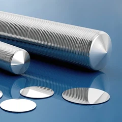


1. Grinding wheel scribing
The grinding wheel dicing machine drives the blade to rotate at high speed through the aerostatic electric spindle to achieve strong grinding of materials. The cutting edges of the blades used are coated with corundum particles. The Mohs hardness of corundum is 10, which is only slightly higher than that of SiC with a hardness of 9.5. Repeated low-speed grinding is not only time-consuming and laborious, but also causes frequent wear of the tool. For example, it takes 6-8 hours to cut a 100 mm (4 inch) SiC wafer, and it is easy to cause chipping defects. Therefore, this traditional inefficient processing method has been gradually replaced by laser scribing.
2. Full laser marking
Laser scribing is the process of using a high-energy laser beam to irradiate the surface of a workpiece to locally melt and vaporize the irradiated area, thereby achieving material removal and scribing. Laser scribing is non-contact processing, without mechanical stress damage, flexible processing methods, no tool loss and water pollution, and low equipment maintenance costs. In order to avoid damage to the supporting film when the laser scribes through the wafer, a UV film resistant to high temperature ablation is used.
At present, laser scribing equipment adopts industrial lasers, with three wavelengths of 1064 nm, 532 nm, and 355 nm, and pulse widths of nanoseconds, picoseconds, and femtoseconds. Theoretically, the shorter the laser wavelength and the shorter the pulse width, the smaller the thermal effect of processing, which is beneficial to micro-precision processing, but the cost is relatively high. The 355 nm ultraviolet nanosecond laser is widely used because of its mature technology, low cost, and small processing thermal effect. In recent years, the 1 064 nm picosecond laser technology has developed rapidly and has been applied to many new fields with good results.
For example, the thermal effect of 355nm ultraviolet laser processing is small, but the incompletely vaporized slag adheres and accumulates in the cutting line, making the cutting section not smooth, and the attached slag is easy to fall off in the subsequent process, affecting device performance. The 1064 nm picosecond laser adopts higher power, high scribing efficiency, sufficient material removal, and uniform cross-section, but the thermal effect of processing is too large, and wider scribing lanes need to be reserved in chip design.
3. Laser half stroke
Laser half-scribing is suitable for processing materials with better cleavability. Laser scribing cuts to a certain depth, and then adopts a split method to generate longitudinally extending stress along the cutting line to separate the chips. This processing method has high efficiency, no need for film sticking and film removal process, and low processing cost. However, the cleavage of silicon carbide wafers is poor, and it is not easy to split. The cracked side is easy to chip, and the slag adhesion phenomenon still exists in the scratched part.
4. Laser invisible cutting
Laser stealth scribing is to focus the laser on the inside of the material to form a modified layer, and then separate the chip by splitting or expanding the film. There is no dust pollution on the surface, almost no material loss, and the processing efficiency is high. The two conditions to achieve stealth scribing are that the material is transparent to the laser, and sufficient pulse energy produces multiphoton absorption.
The band gap energy Eg of silicon carbide at room temperature is about 3.2 eV, which is 5.13×10 -19 J. 1 064 nm laser photon energy E=hc/λ=1.87×10 -19 J. It can be seen that the laser photon energy of 1 064 nm is smaller than the absorption band gap of silicon carbide material, and it is optically transparent, which meets the conditions of invisible scribing. The actual transmittance is related to factors such as material surface properties, thickness, and dopant types. Taking a polished silicon carbide wafer with a thickness of 300 μm as an example, the measured 1064 nm laser transmittance is about 67%.
The picosecond laser with extremely short pulse width is selected, and the energy generated by multiphoton absorption is not converted into heat energy, but only causes a certain depth of modified layer inside the material. The modified layer is the crack area, melting area or refractive index change area inside the material. Then through the subsequent splitting process, the grains will be separated along the modified layer.
The cleavability of silicon carbide material is poor, and the distance between modified layers should not be too large. The test uses a JHQ-611 automatic dicing machine and a 350 μm thick SiC wafer to cut 22 layers at a cutting speed of 500 mm/s. After cracking, the section is relatively smooth, with small chipping and neat edges.
5. Water guided laser cutting
The water guide laser focuses the laser light and guides it into the micro-water column. The diameter of the water column varies according to the nozzle aperture, and there are various specifications of 100-30 μm. Using the principle of total reflection between the water column and the air interface, the laser light will propagate along the direction of the water column after being introduced into the water column.
It can process within the range where the water column remains stable, and the super-long effective working distance is especially suitable for cutting thick materials. In traditional laser cutting, the accumulation and conduction of energy is the main cause of thermal damage on both sides of the cutting line, while the water-guided laser quickly takes away the residual heat of each pulse without accumulating on the workpiece due to the action of the water column, so cutting The way is clean and neat.
Based on these advantages, water-conducting laser cutting silicon carbide is a good choice in theory, but the technology is difficult, and the maturity of related equipment is not high. It is difficult to manufacture nozzles as vulnerable parts. If the fine water column cannot be accurately and stably controlled, The splashed water droplets ablate the chip, affecting the yield. Therefore, this process has not yet been applied to the production of silicon carbide wafers.
Dicing Method Of Silicon Carbide Wafer
Jul 10, 2023
Leave a message
You Might Also Like


